- To connect lights to the board, first ensure that any power input connected to the board is turned off.
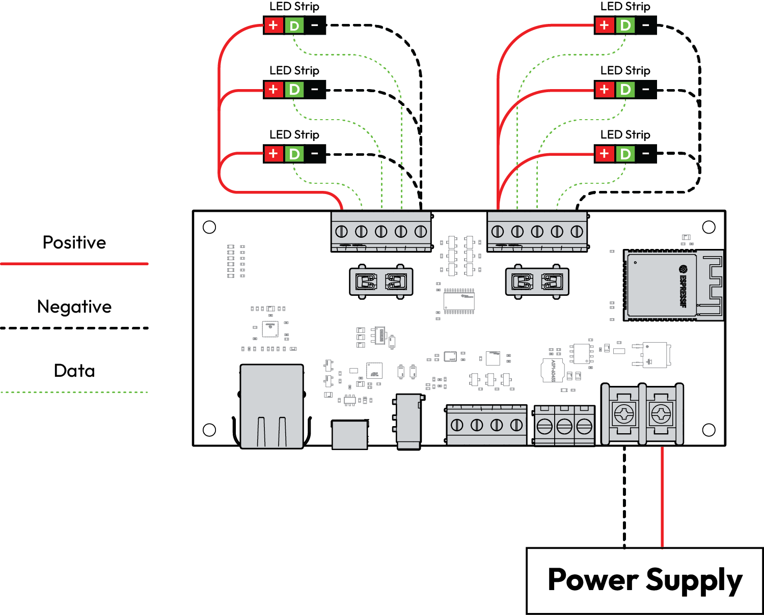
- The Eternaglo Plus supports up to (6) LED strips. WLED supports a variety of different individually addressable LEDs. More information is available here on supported LED types.
- For most individually addressable LEDs, they will require power, ground, and data connections. To connect this type of LED strip to the board, connect the LED power input to the 5-24V output on the board, the ground to GND, and the data to one of the IO terminals. Individually addressable LEDs are directional, so one end is solely for input and the other for output. Be sure to only connect the LED input to the Eternaglo board. If connecting multiple LED strips the 5-24V and GND terminals can be shared, but ensure to use a separate IO terminal for the data connection for each LED strip.
Connections can be made by either stripping a small bit (~1/4”) of insulation off of each wire, inserting the bare wire into the terminal, then tightening the screw, or by crimping a ferrule connector to each wire first, then inserting the connector into the terminal and tightening (recommended). - Now that the LED strips are hooked up, turn power to the board back on. If the LEDs don’t light up, don’t worry, you must first configure WLED so it knows which IO is being used to control the LED strips. To do this, open WLED on your phone or computer, then click the “Config” cog. From here go to “LED Preferences”. First, ensure that the LED type matches the LEDs you have connected in the dropdown under “LED Outputs”. By default it will likely be set to “WS281x”. If you’re using a different type of LED, select the corresponding type in the dropdown. You may also have to switch the Color Order later if the LED colors don’t match what the app is showing. Next, tell WLED how many LEDs are being controlled in the first IO that’s connected. If the LED strip has 100 LEDs, ensure that the “Length” is set to 100. Now change the GPIO number to match the IO terminal that the LED data line is connected to. For example, if the data is connected to IO12, then enter “12” in the GPIO box. You can now choose “Save” to apply the new settings. If done correctly, your LEDs should light up!
- If you have multiple LED strips connected, you can add them by again entering the LED Preferences, then under LED Outputs choosing the “+” sign. This will allow you to choose the LED type, color order, length, and GPIO for the second LED strip. Repeat this step for as many strips as you have connected to the board.
- You are now ready to start using WLED! For additional information on setting presets, schedules, and dividing your LEDs into zones, visit the resources section of our website. We hope you enjoy using your new Eternaglo product!